ASCE 7-22 and the Phoenix-Tempe area amendments to the IBC require geophysical data when site conditions suggest lateral variability in the subsurface. In Tempe, where basin-fill sediments interbed with cemented caliche layers and the occasional buried pediment surface, seismic tomography becomes a practical tool for mapping velocity contrasts before excavation. We deploy seismic refraction and reflection arrays to image depth-to-bedrock, identify paleochannel incisions, and assess rippability in the upper 30 meters. The August 2023 IBC references ASTM D5777 for downhole seismic methods, and our field setup follows those guidelines for shallow targets. In the context of Tempe’s explosive urban growth near the Loop 101 and Apache Boulevard corridors, understanding subsurface geometry through seismic refraction profiles helps avoid surprises when designing footings or deep excavations in mixed alluvial deposits.
Velocity contrasts below 1,200 m/s often indicate uncemented basin fill in Tempe; caliche layers jump above 2,000 m/s and change excavation plans immediately.
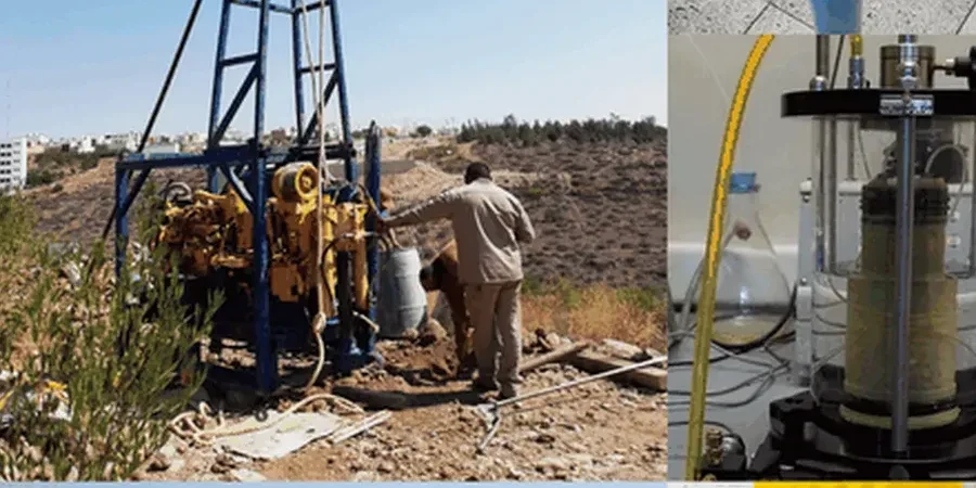
Scope of work in Tempe Arizona
Risks and considerations in Tempe Arizona
In Tempe, we frequently see refraction surveys misinterpreted when a thin high-velocity caliche layer masks lower-velocity material beneath it — a classic hidden-layer problem. The calcrete horizons common south of Tempe Town Lake, formed by Pleistocene pedogenic processes, can create a velocity inversion that first-arrival tomography alone cannot detect. If the geophysicist doesn't cross-check with a reflection profile or a borehole log, the interpreted bedrock depth can be off by several meters. That error cascades into excavation quantities and foundation design assumptions. Another practical issue: summer fieldwork between June and September, when surface temperatures exceed 110°F, introduces near-surface velocity variations that require careful static corrections. We run early-morning lines whenever possible and monitor ground coupling continuously to avoid data degradation.
Our services
Our Tempe-based seismic tomography services cover the full workflow from line layout to final interpretation. Each survey is configured for the specific depth target and site access constraints of the job.
Seismic Refraction Tomography
2D P-wave velocity profiling for rippability assessment, depth-to-bedrock, and site class determination per IBC. Typical line lengths of 70-115 meters, resolving layers down to 30 meters in Tempe basin fill.
Seismic Reflection Profiling
High-resolution imaging of stratigraphic boundaries and buried fault structures using CDP processing. Useful where refraction methods encounter velocity inversions in interbedded caliche sequences.
MASW Joint Inversion
Combined refraction and surface-wave tomography to map both P-wave and S-wave velocity structure. Delivers Vs30 values directly applicable to ASCE 7 site classification.
Quick answers
What does a seismic tomography survey cost for a standard site in Tempe?
For a typical residential or small commercial lot in Tempe with one or two refraction lines of 70-100 meters each, the total cost ranges from US$3,130 to US$5,300. The final figure depends on line length, number of spreads, access constraints, and whether reflection or MASW data is collected simultaneously. We provide a fixed-price quote after reviewing the site layout and depth targets.
How deep can refraction tomography see in the Tempe basin sediments?
With a 115-meter spread and a sledgehammer source, refraction penetration typically reaches 25 to 35 meters in the sands and gravels of the Salt River basin. When caliche layers are present, the high-velocity cap can limit depth unless we use a heavier source or supplement with reflection profiling.
Does seismic tomography help determine the IBC site class for my Tempe project?
Yes, indirectly. Refraction gives you P-wave velocity, but site class per IBC Table 1613.2.3 requires shear-wave velocity (Vs30). We usually run MASW alongside refraction to measure Vs directly. The combined dataset provides both the velocity model for excavation planning and the Vs30 value for structural design.